An Accurate, Inexpensive Attitude Determination and Control System for CubeSats by Duarte Rondão, Cass Hussmann and Afzal Suleman Part 4
From The Space Library
IV. Attitude Control
For the scope of this work, the attitude control for ECOSat-III is divided into two main parts: detumbling and nadir-tracking. Detumbling, or despin, consists of bringing the satellite’s rotation rates close to zero after separation. This is typically done by resorting to a magnetometer and magnetorquer combination, since the rotation rates are typically too high to acquire line-of-sight measurements. The classical way to despin from arbitrary initial tumbling is achieved with the so-called B-dot law [12], by commanding the  magnetorquer dipole according to
 ,
,  ,
,  , (IV.1)
where  is the derivative of the component of the magnetic field expressed in frame
  and
and  is a constant gain.
is obtained directly by differentiating the output of the satellite magnetometer. However, if this measurement is noisy, its derivative will be more so.
An improved solution is given in [13]. The commanded magnetic torque is given by:
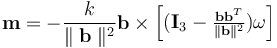 (IV.2)
This leads to the control law
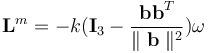 (IV.3)
A criterion on how to estimate the gain is given in [13].
Nadir-tracking consists of keeping the body frame, , aligned with the orbital frame,  . To achieve this, a sliding controller for the reaction wheels with quaternion and angular velocity feedback is employed [1,14]:
 (IV.4a)
 (IV.4b)
Here, 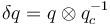 is the error quaternion,
  is the commanded quaternion,
  is the corresponding commanded angular velocity,
 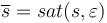 , sat (.) is the saturation function,
  are positive quantities and
  is a positive definite matrix.
The application of a constant or rising torque causes an increase in the reaction wheel’s rotational speed, which may lead to saturation. To prevent this, the magnetorquers are used to dump momentum from the reaction wheels using a cross-product law [15]:
 (IV.5)
